24 Sep 2019
Our lab recently implemented a timed watering system for our Arabidopsis growth chambers. This system is cheap and easy to build and operate, and uses widely-available hydroponics equipment. It accommodates fertilizer application and allows for relatively precise watering of individual trays. Our growth chambers are walk-in rooms with two levels of platforms for growing plants on either side of the room. Each platform can hold 8 trays (each with 32 single pots).
The equipment list described here is sufficient to equip all 4 platforms in a single room (i.e. water 32 trays, or 1,024 individual Arabidopsis plants) with separate timing for each side (i.e. each side of the room can have different watering regimes). Please scale according to your own needs.
Overall Layout
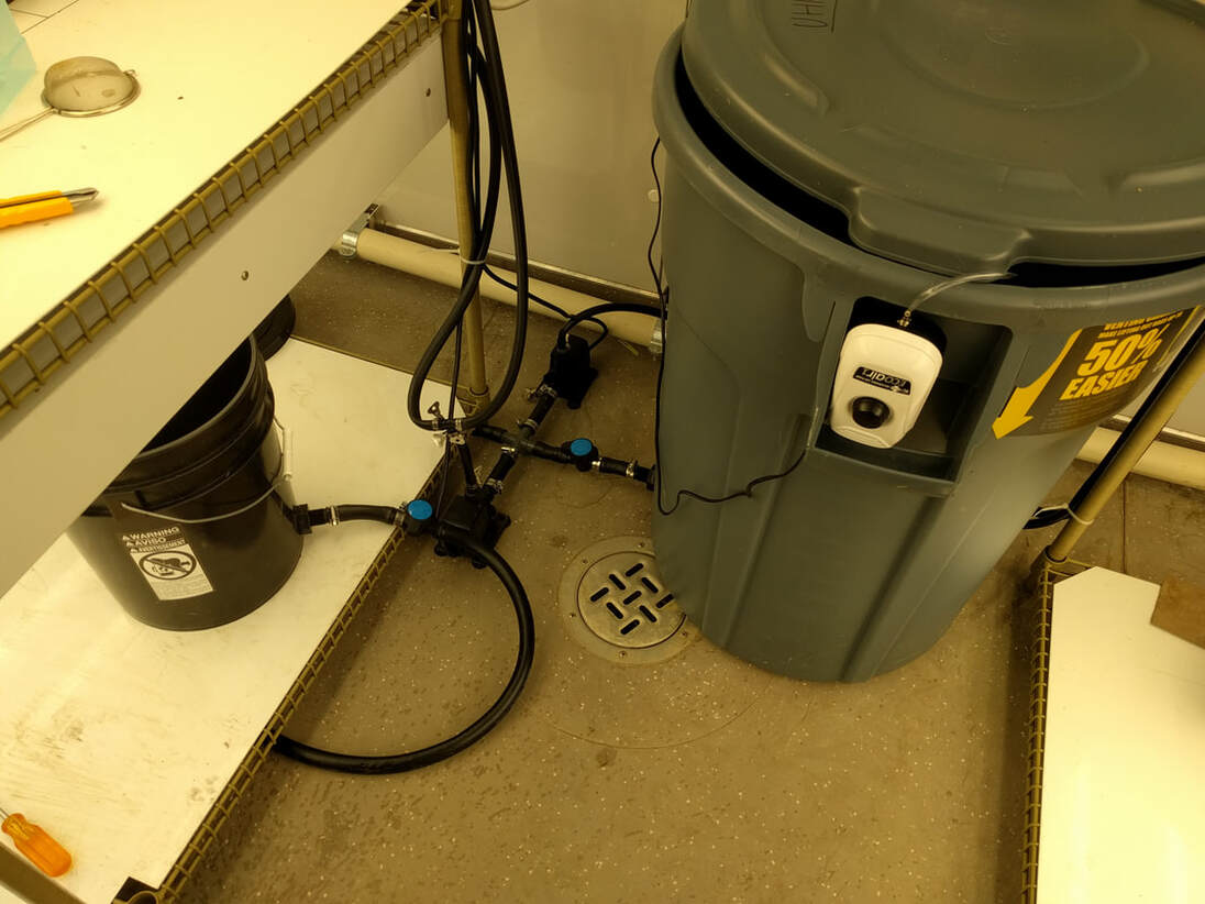
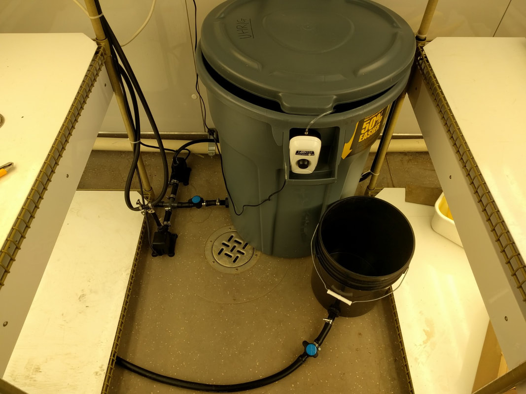
The final set up is shown in the first picture on this page. We use a large garbage can as a water tank and a smaller bucket as a tank containing fertilizer solution. Both the tanks have outlets at the bottom that feed into two valves (blue knobs). Valves control flow of water/fertilizer from each tank to two separate intakes of the the 4-way connector (center). The other two connectors are attached to two separate pumps, each of which supply plants grown on either side of our walk-in chamber. The pumps each have an outlet at the top from which tubing is connected to a T-junction. The two outlets of the T-junction lead to separate tubing supplying the two different growth platforms in our chamber (upper and lower).
Equipment List
Equipment was purchased from a local hydroponics store but links to identical/similar items from Amazon Canada are provided where available. The outline quantity of items is what was used to outfit one growth room:
Tools
Setting up the water source
1. Watering source
- The 44 gallon garbage can serves as our water tank.
- Turn the garbage can upside down to drill a hole in it's side at the bottom.
- This will be the water outlet connected to the pump.
2. Drill hole with the 3/4" diameter hole saw drill bit (Figure 1-2).
NOTE: 3/4" pipe allows for maximal flow from bucket (tank) to distribution pump.
- Hold drill against the side of the garbage can (watering tank), about 6cm from the bottom (Figure 1 & 2).
- Start drilling, applying gentle pressure to punch a hole through the can (Figure 1).
- Clean the sides of the hole with your hands or a pair of scissors to remove excess material.
Our lab recently implemented a timed watering system for our Arabidopsis growth chambers. This system is cheap and easy to build and operate, and uses widely-available hydroponics equipment. It accommodates fertilizer application and allows for relatively precise watering of individual trays. Our growth chambers are walk-in rooms with two levels of platforms for growing plants on either side of the room. Each platform can hold 8 trays (each with 32 single pots).
The equipment list described here is sufficient to equip all 4 platforms in a single room (i.e. water 32 trays, or 1,024 individual Arabidopsis plants) with separate timing for each side (i.e. each side of the room can have different watering regimes). Please scale according to your own needs.
Overall Layout
The final set up is shown in the first picture on this page. We use a large garbage can as a water tank and a smaller bucket as a tank containing fertilizer solution. Both the tanks have outlets at the bottom that feed into two valves (blue knobs). Valves control flow of water/fertilizer from each tank to two separate intakes of the the 4-way connector (center). The other two connectors are attached to two separate pumps, each of which supply plants grown on either side of our walk-in chamber. The pumps each have an outlet at the top from which tubing is connected to a T-junction. The two outlets of the T-junction lead to separate tubing supplying the two different growth platforms in our chamber (upper and lower).
Equipment List
Equipment was purchased from a local hydroponics store but links to identical/similar items from Amazon Canada are provided where available. The outline quantity of items is what was used to outfit one growth room:
- 2x ECO 264 Fixed Flow Pump 290 GPH (or equivalent hydroponics pump)
- 1x ECO Air1 Adjustable Air Pump
- 1x Air Stone (or any air stone sized for your water barrel)
- 25 feet Airline Tubing
- 2x Apollo 9 Two Outlet Digital Timer
- 8 feet 3/4 inch black tubing
- 100 feet 1/2 inch flexible black tubing
- 20 feet 1/4 inch drip irrigation tubing
- 32x Universal drip irrigation 1/4" couplers
- 32x Spot watering drippers (1 gallon per hour)
- 32x Drip irrigation 1/4" plugs
- 2x 1/2" T-junction fitting
- 1x 3/4" Cross barbed fitting
- 4x 3/4" plugs
- 1x 44 gallon garbage can (Watering Tank)
- 1x 5 gallon bucket (Fertilizer Tank)
- 2x 3/4" barbed bulkhead
Tools
- Sharp blade / shears / scissors to cut through tubing
- Measuring tape
- Drill
- Caulking gun & common caulk
- Hole-saw drill bit
Setting up the water source
1. Watering source
- The 44 gallon garbage can serves as our water tank.
- Turn the garbage can upside down to drill a hole in it's side at the bottom.
- This will be the water outlet connected to the pump.
2. Drill hole with the 3/4" diameter hole saw drill bit (Figure 1-2).
NOTE: 3/4" pipe allows for maximal flow from bucket (tank) to distribution pump.
- Hold drill against the side of the garbage can (watering tank), about 6cm from the bottom (Figure 1 & 2).
- Start drilling, applying gentle pressure to punch a hole through the can (Figure 1).
- Clean the sides of the hole with your hands or a pair of scissors to remove excess material.
Build your own Timed Watering System
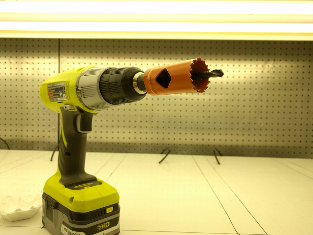
Figure 1: Drill with hole saw drill bit
|

Figure 2: Drilled watering tank
|
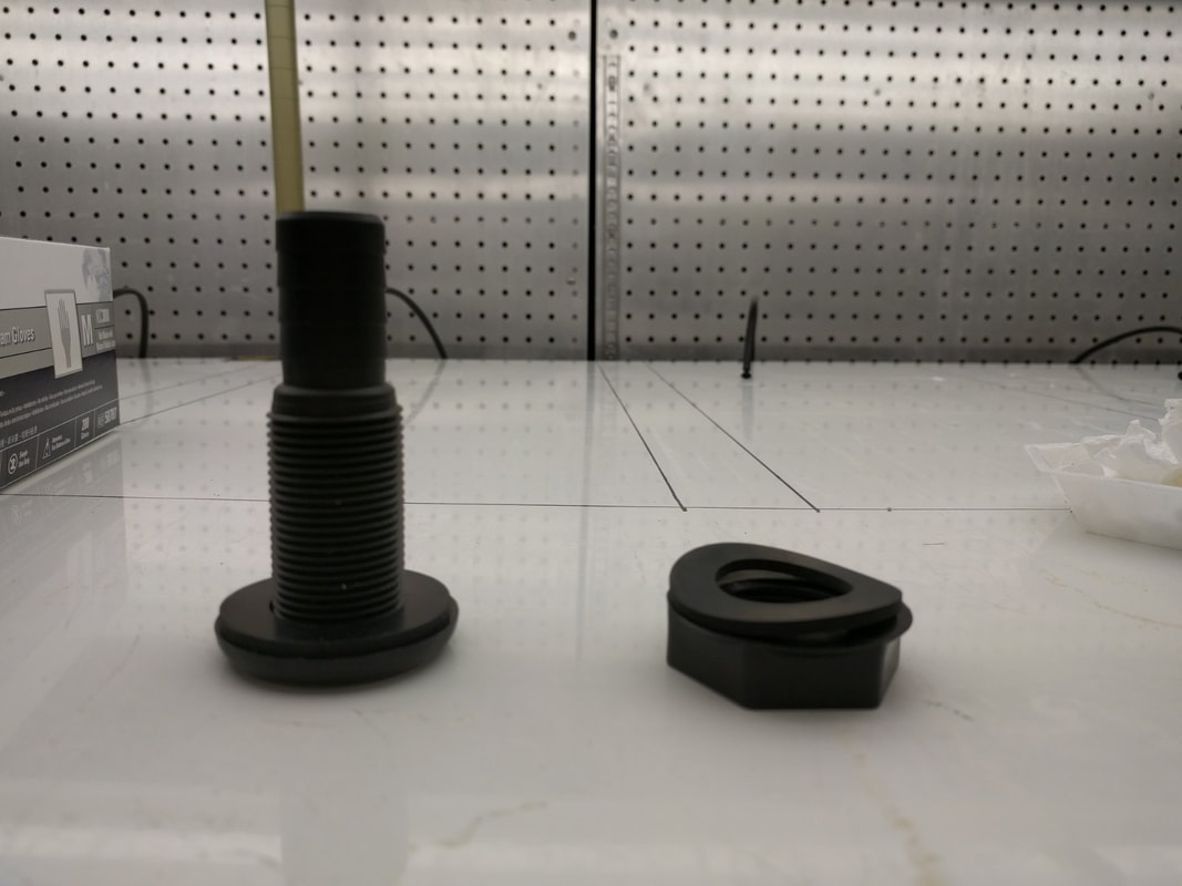
Figure 3: Bulkhead assembly
|
3. Bulkhead Installation (Figure 3-4):
- Install the 3/4" barbed bulkhead to the hole ensuring that the spigot is protruding from the tank (Figure 3).
NOTE: The protruding spigot is what the piping will be attached too.
- Secure spigot to watering tank by tightening the screw (Figure 4).
4. Follow the same procedure in step 2-3 to attach a bulkhead to the smaller fertilizer tank:
- Install the 3/4" barbed bulkhead to the hole ensuring that the spigot is protruding from the tank (Figure 3).
NOTE: The protruding spigot is what the piping will be attached too.
- Secure spigot to watering tank by tightening the screw (Figure 4).
4. Follow the same procedure in step 2-3 to attach a bulkhead to the smaller fertilizer tank:
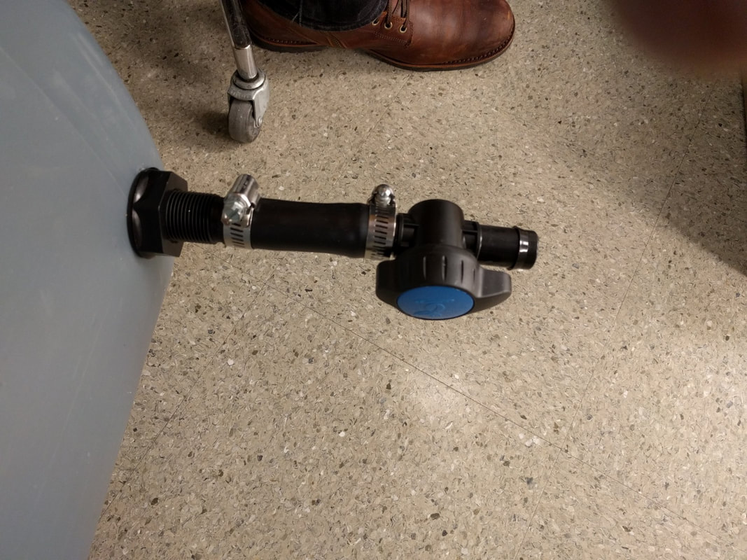
Figure 4: Valve attachment to bulkhead.
|
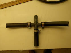
Figure 5: 4-way connector assembly. |
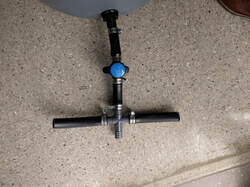
Figure 6: connecting valves to 4-way connector.
|
5. Valve assembly (Figure 4):
- Take short sections of the 3/4" tubing and attach to one end of the valve. Secure using a 3/4" tube clamp.
- Attach the other end of the valve tubing to the bulkhead of the water tank.Secure using a 3/4" tube clamp.
- Similarly, attach the other valve to the bulkhead of the fertilizer tank and perform steps as described above.
6. Valve integration (Figure 5 & 6):
- Attach short sections of 3/4" tubing with a 3/4" clamp to each of the 4-way connectors (Figure 5).
- Attach both the watering & fertilizer bucket to the 4-way connector using a small length of 3/4" tubing and clamps (Figure 6).
- Take short sections of the 3/4" tubing and attach to one end of the valve. Secure using a 3/4" tube clamp.
- Attach the other end of the valve tubing to the bulkhead of the water tank.Secure using a 3/4" tube clamp.
- Similarly, attach the other valve to the bulkhead of the fertilizer tank and perform steps as described above.
6. Valve integration (Figure 5 & 6):
- Attach short sections of 3/4" tubing with a 3/4" clamp to each of the 4-way connectors (Figure 5).
- Attach both the watering & fertilizer bucket to the 4-way connector using a small length of 3/4" tubing and clamps (Figure 6).
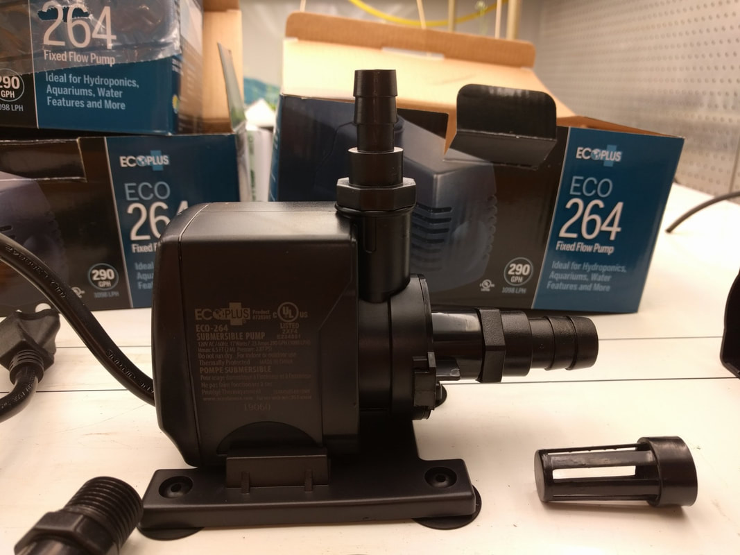
Figure 7: Pump setup - 3/4" intake (horizontal) / 1/2" output (vertical).
|
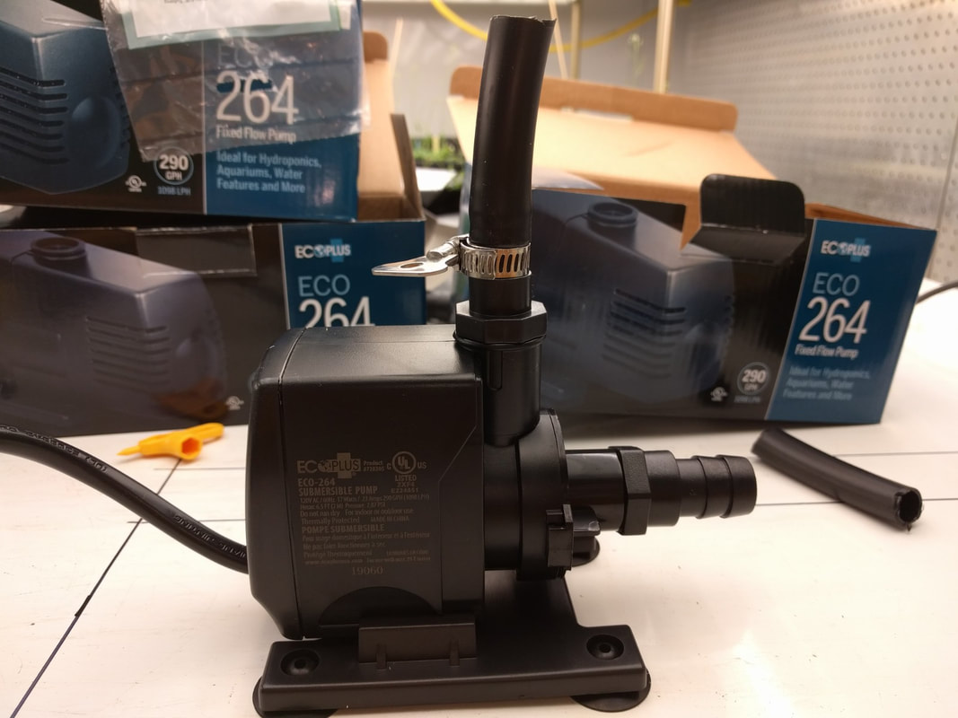
Figure 8: Fix 3/4" intake (horizontal) / 1/2" output (vertical) piping with 3/4" & 1/2" clamps.
|
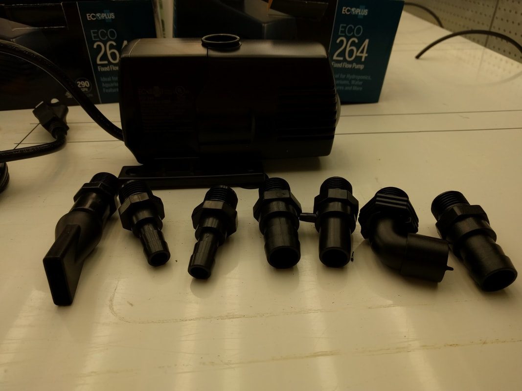
Figure 9: ECO pump inlet and outlet options.
|
7. Pump assembly (Figure 7-10):
- Follow the instruction booklet provided with the pump and connect the 3/4" fitting (provided with the pump) to the inlet (bottom) and the 1/2" fitting to the outlet (top) of the pump (Figure 7-8).
NOTE: Using 1/2" tubing for water distribution keeps pressure more even throughout all distribution piping.
NOTE: Each ECO pump comes with capability to attach various diameter tubing to the inlet and outlet as well as permit the submergence of the pump if desired (Figure 9).
- Attach each pump (2x pumps = 4 water lines here) to the 4-way connector through the bottom inlet using a small segment of 3/4" piping and securing with a 3/4" clamp (Figure 10).
NOTE: If using only a single pump, use a T-junction instead of a 4-way connector.
NOTE: If running multiple lines over long distances or have to pump water vertically, consider using a different pump. Each pump of the ECO line comes with a guide relating their capabilities to distribute water vertically and over distance.
NOTE: From this point on in the instructions everything should be performed in duplicate for each side of the growth room.
- Follow the instruction booklet provided with the pump and connect the 3/4" fitting (provided with the pump) to the inlet (bottom) and the 1/2" fitting to the outlet (top) of the pump (Figure 7-8).
NOTE: Using 1/2" tubing for water distribution keeps pressure more even throughout all distribution piping.
NOTE: Each ECO pump comes with capability to attach various diameter tubing to the inlet and outlet as well as permit the submergence of the pump if desired (Figure 9).
- Attach each pump (2x pumps = 4 water lines here) to the 4-way connector through the bottom inlet using a small segment of 3/4" piping and securing with a 3/4" clamp (Figure 10).
NOTE: If using only a single pump, use a T-junction instead of a 4-way connector.
NOTE: If running multiple lines over long distances or have to pump water vertically, consider using a different pump. Each pump of the ECO line comes with a guide relating their capabilities to distribute water vertically and over distance.
NOTE: From this point on in the instructions everything should be performed in duplicate for each side of the growth room.
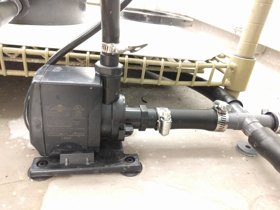
Figure 10: Pump attached to 4-way connector.
|
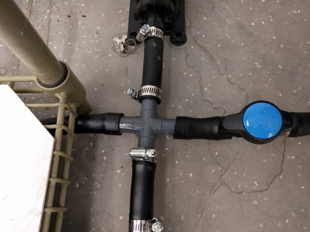
Figure 11: Top view of assembled 4-way connector.
|
8. Complete 4-way connected 2-pump system (Figure 10 & 11):
- Once assembled be sure to pay careful attention to which tank (water or fertilizer) is being drawn from for watering.
- Ensure that the valve to the unused tank is closed.
9. Measure out complete distance to been lined with 1/2" feed line tubing (Figure 12-15):
- As the 1/2" watering feed line tubing will be connected to the pumping system next, accurate measurement of 1/2" watering feed line should be undertaken a this point.
NOTE: Leaving a little extra feed line should not affect performance (may be system dependent). However, performance will depend: 1. the pump being used and 2. on how high and far the water is to be pumped.
- Once assembled be sure to pay careful attention to which tank (water or fertilizer) is being drawn from for watering.
- Ensure that the valve to the unused tank is closed.
9. Measure out complete distance to been lined with 1/2" feed line tubing (Figure 12-15):
- As the 1/2" watering feed line tubing will be connected to the pumping system next, accurate measurement of 1/2" watering feed line should be undertaken a this point.
NOTE: Leaving a little extra feed line should not affect performance (may be system dependent). However, performance will depend: 1. the pump being used and 2. on how high and far the water is to be pumped.
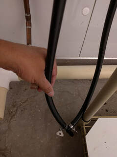
Figure 12: Connection of T-junction to 1x pump line into 2x watering feed lines.
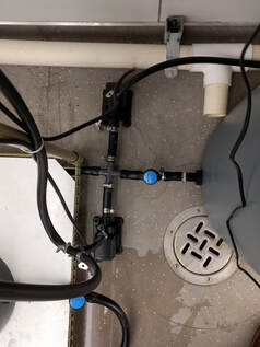
Figure 13: Pump connection to watering feed line
|
10. Connect the watering feed line to the pump (top outlet; Figure 10):
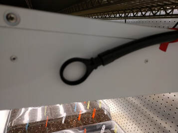
NOTE: Be sure to completely measure ALL feed line tubing distances to be lined with 1/2" piping prior to this step. See step 9. - Using a short piece of 1/2" tubing and a 1/2" clamp attach the pump to the T-junction (Figure 12). NOTE: In this setup we are running 2x watering lines from one pump. If a single line is to be used directly attach the watering feed line to the pump outlet (top outlet). - The system is now complete (Figure 13). 11. Plug watering feed line (Figure 14): - Ensure that the end of the watering feed line is plugged with a 1/2" tubing plug (Figure 14).
|
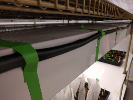
12. Fasten the watering feed line along the route from which watering will be conducted (Figure 15):
- In our experience, tape and/or zip ties will suffice for fastening watering feed line along its route.
- It is better to allow for easy watering feed line removal so that alternative watering setups can be adapted experimentation needs.
- In our experience, tape and/or zip ties will suffice for fastening watering feed line along its route.
- It is better to allow for easy watering feed line removal so that alternative watering setups can be adapted experimentation needs.
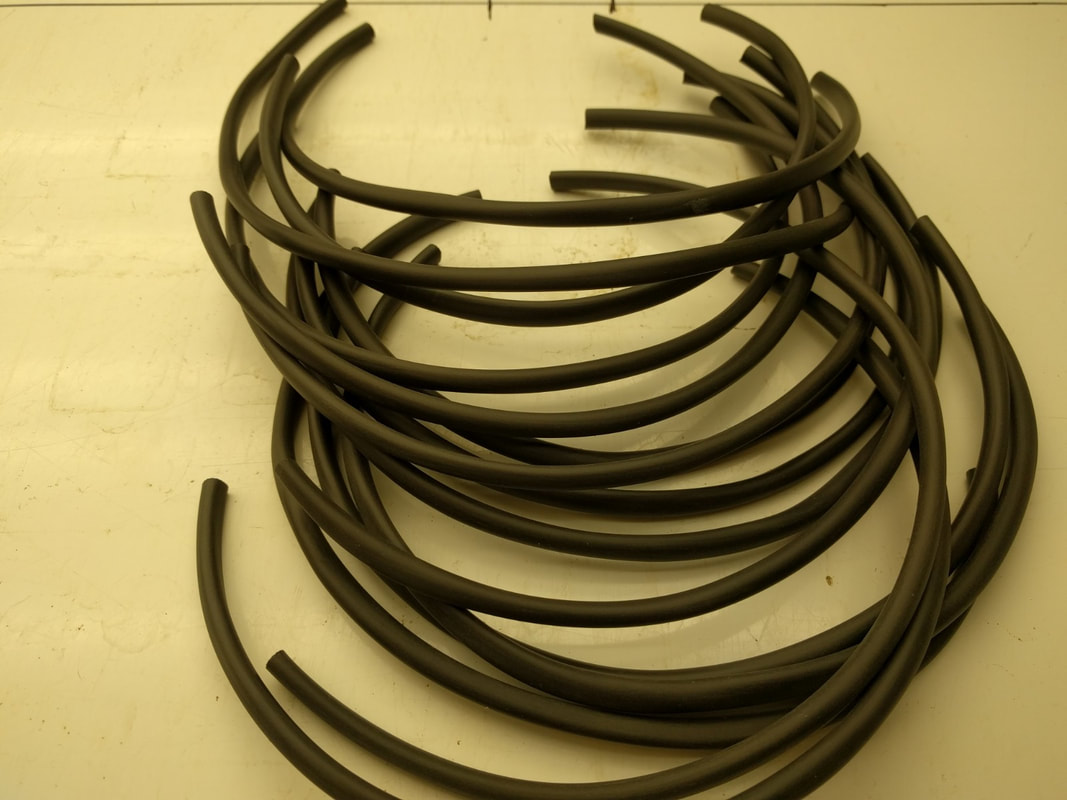
Figure 16: Evenly cut 1/4" drip irrigation tubing as needed to connect to the watering feed line.
|
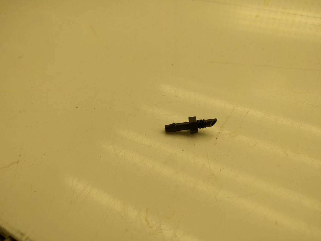
Figure 17: fasten 1/4" universal drip irrigation couplers to one end of each piece of 1/4" irrigation tubing.
|
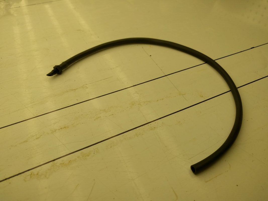
Figure 18: An assembled 1/4" drip irrigation tubing with irrigation coupler.
|
13. Create multiple drip irrigation lines (Figure 16-18):
- Cut equal lengths of the 1/4" drip irrigation tubing (~30cm each is ideal for most uses) (Figure 16)
NOTE: These should be equal length to ensure equal watering across trays.
- Insert a universal drip irrigation coupler into the end of each irrigation line (Figure 17) to create the setup to be connected to the 1/2" watering feed line (Figure 18).
NOTE: 1/4" drip line plugs are available to plug lines not being used at the end of the irrigation drip line.
- Cut equal lengths of the 1/4" drip irrigation tubing (~30cm each is ideal for most uses) (Figure 16)
NOTE: These should be equal length to ensure equal watering across trays.
- Insert a universal drip irrigation coupler into the end of each irrigation line (Figure 17) to create the setup to be connected to the 1/2" watering feed line (Figure 18).
NOTE: 1/4" drip line plugs are available to plug lines not being used at the end of the irrigation drip line.
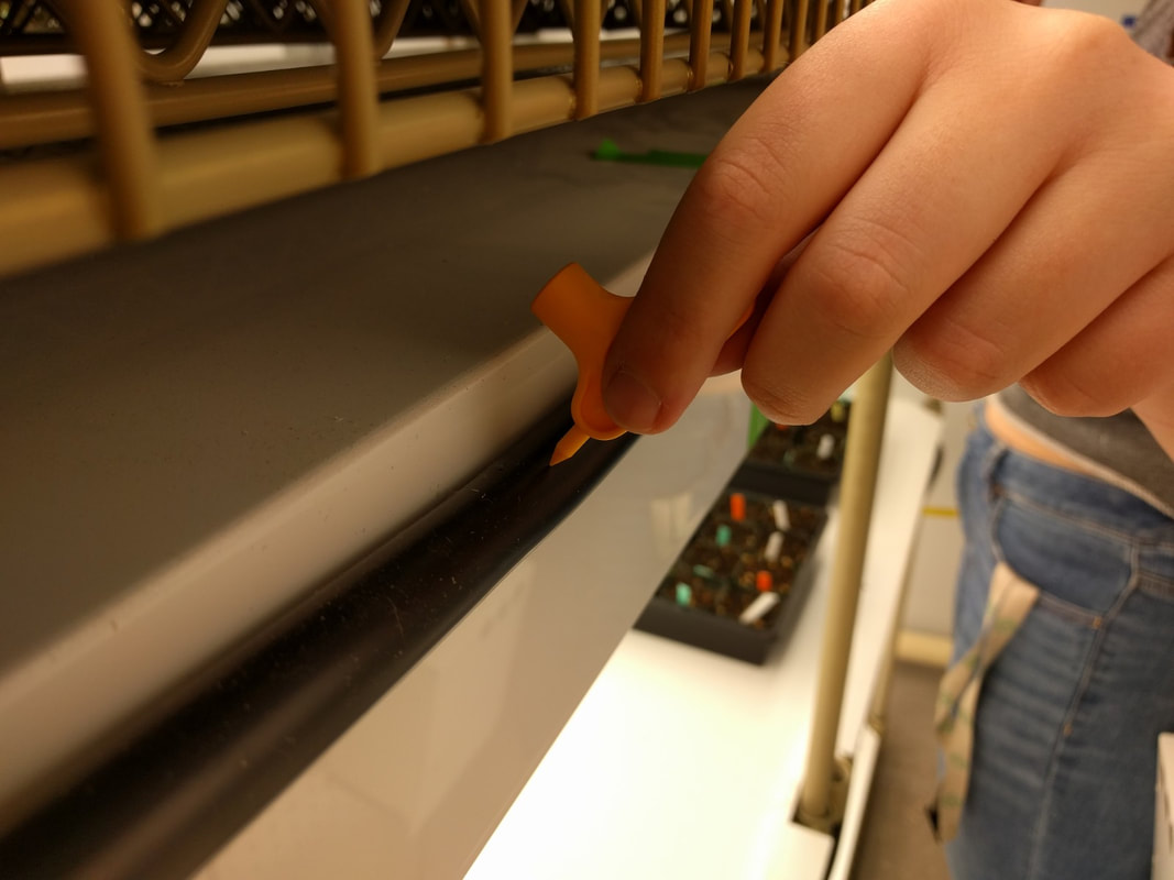
Figure 19: Puncturing the watering feed line.
|
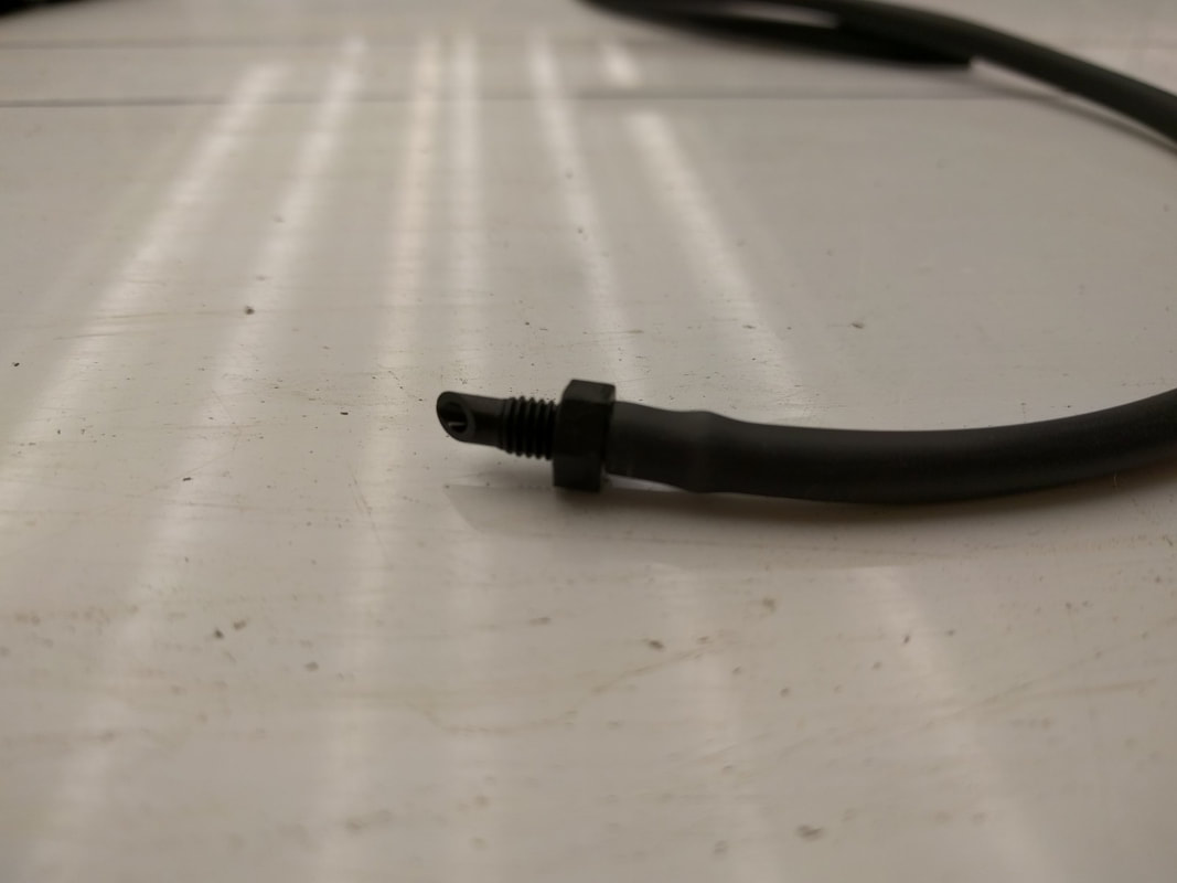
Figure 20: universal irrigation line coupled 1/4" drip line to be inserted into the punctured 1/2" watering feed line.
|
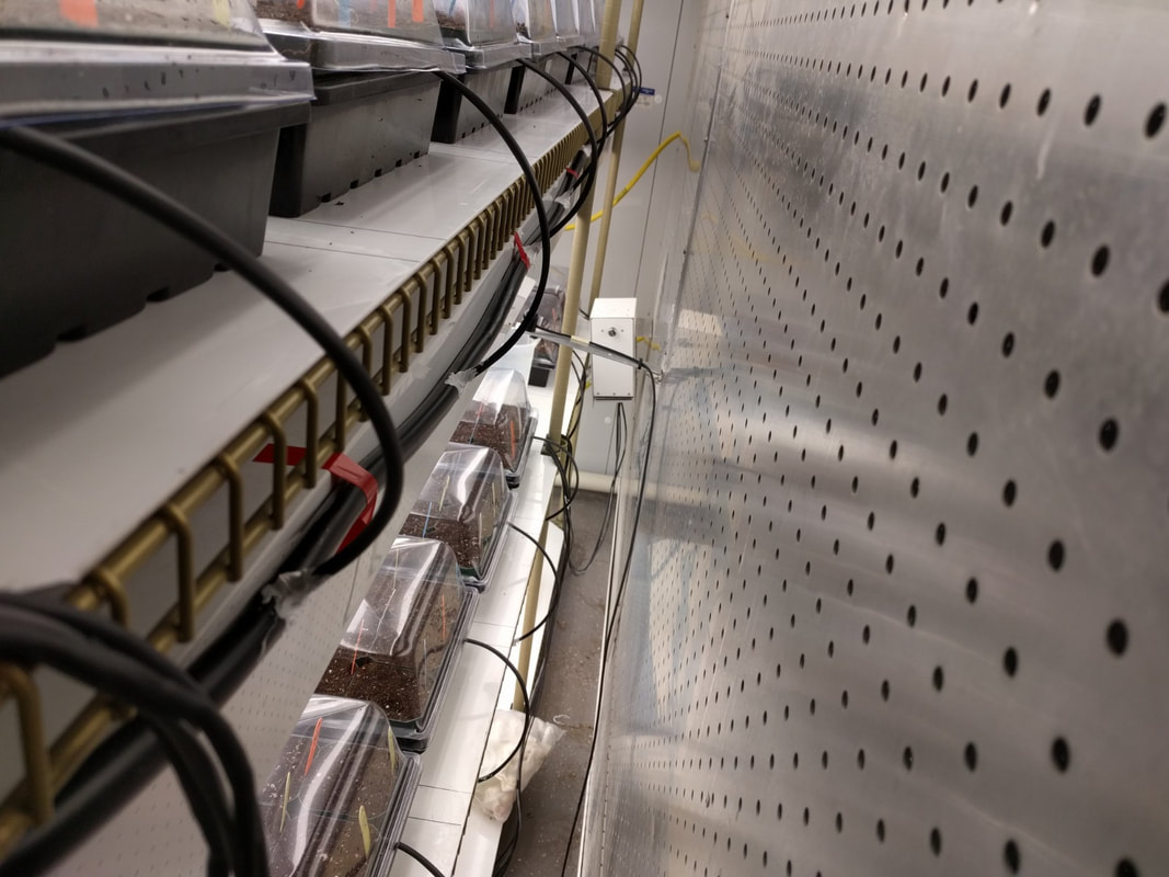
Figure 21: Fastened drip lines.
|
14. Fasten the 1/4" drip lines to the 1/2" watering feed line (Figure 19-21):
- Using the a sharp object with a point end smaller than the universal irrigation line coupler, puncture the 1/2" watering feed line as positions equal distance from each other and that align with the trays that are to be irrigated.
NOTE: The number of holes may vary if you are watering each plant individually.
- Using the a sharp object with a point end smaller than the universal irrigation line coupler, puncture the 1/2" watering feed line as positions equal distance from each other and that align with the trays that are to be irrigated.
NOTE: The number of holes may vary if you are watering each plant individually.
15. Spot watering drippers:
- Attached the 1 gallon / hr spot watering drippers to the ends of the irrigation lines.
NOTE: Their are many flow rates available.
NOTE: The amount of water distributed out these lines will be consistent, which means total water applied will be a combination of flow rate and time.
- Attached the 1 gallon / hr spot watering drippers to the ends of the irrigation lines.
NOTE: Their are many flow rates available.
NOTE: The amount of water distributed out these lines will be consistent, which means total water applied will be a combination of flow rate and time.
|
|
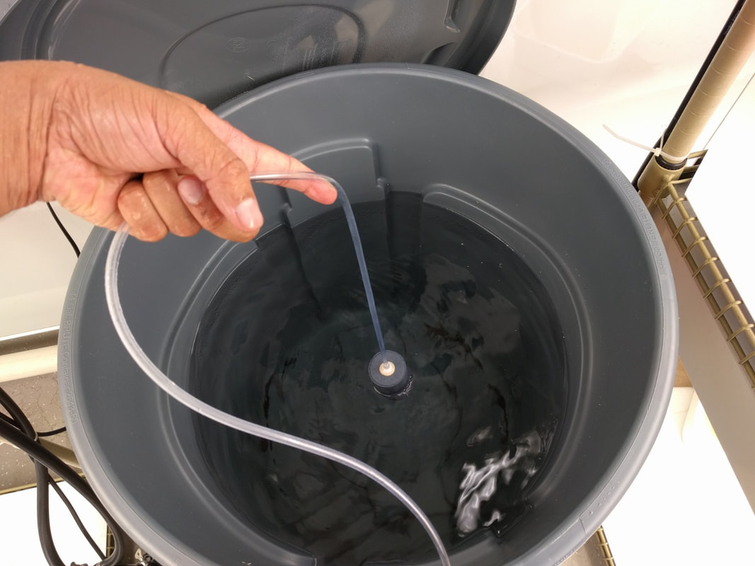
16. Assemble aeration device.
- Attach the airline tubing to the air stone.
- Attach the airline to the ECO air1 adjustable air pump.
- Lower the stone into the watering tank.
- Plug the ECO air1 adjustable air pump into the wall to ensure constant aeration.
17. Powering the pump.
- Plug the ECO 264 Fixed Flow Pump(s) (in our setup 2x pumps = 4 watering lines) to the timer sockets of the Apollo 9 Two Outlet Digital Timer.
- Set timer accordingly.
18. Other recommendations.
- Check for leaks before relying on the system for watering.
- Ensure that your watering is in tune with plant needs to prevent over watering.
- Attach the airline tubing to the air stone.
- Attach the airline to the ECO air1 adjustable air pump.
- Lower the stone into the watering tank.
- Plug the ECO air1 adjustable air pump into the wall to ensure constant aeration.
17. Powering the pump.
- Plug the ECO 264 Fixed Flow Pump(s) (in our setup 2x pumps = 4 watering lines) to the timer sockets of the Apollo 9 Two Outlet Digital Timer.
- Set timer accordingly.
18. Other recommendations.
- Check for leaks before relying on the system for watering.
- Ensure that your watering is in tune with plant needs to prevent over watering.